« View all new features in
Mathematica
9
◄
previous
|
next
►
New in
Mathematica
9
›
Enhanced Control Systems
Control an RLC Circuit Modeled as a Descriptor System
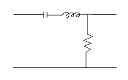
This resistor-inductor-capacitor circuit can easily be modeled from the component equations using a descriptor state-space model.
In[1]:=
X
{ind, cap, res} = {l i'[t] == Subscript[v, l][t], Subscript[v, c]'[t] == 1/c i[t], r i[t] == Subscript[v, r][t]}; kirchhoff = Subscript[v, l][t] + Subscript[v, c][t] + Subscript[v, r][t] == Subscript[v, s][t];
In[2]:=
X
circuit = StateSpaceModel[{ind, cap, res, kirchhoff}, {i[t], Subscript[v, l][t], Subscript[v, c][t], Subscript[v, r][t]}, {Subscript[v, s][t]}, {i[t]}, t]
Out[2]=
In[3]:=
X
circuit = StateSpaceModel[{ind, cap, res, kirchhoff}, {i[t], Subscript[v, l][t], Subscript[v, c][t], Subscript[v, r][t]}, {Subscript[v, s][t]}, {Subscript[v, r][t]}, t]
Out[3]=
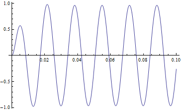
The magnitude response of the system should be reduced at the utility frequency.
In[4]:=
X
circuit = circuit /. {r -> 4, c -> 1/1000, l -> 1/100};
In[5]:=
X
y0 = OutputResponse[circuit, Sin[2 Pi 60 t], {t, 0, .3}]; Plot[y0, {t, 0, .1}, ImageSize -> Medium]
Out[5]=
Find a controller to place the closed-loop poles at symbolic locations.
In[6]:=
X
k = Simplify@StateFeedbackGains[circuit, {re + I im, re - I im}]; csys = SystemsModelStateFeedbackConnect[circuit, k];
Find the responses when the poles are moved away from the origin along each axis.
In[7]:=
X
TransferFunctionPoles[circuit]
Out[7]=
In[8]:=
X
y1 = OutputResponse[csys /. {re -> -800, im -> 100 Sqrt[6]}, Sin[2 \[Pi] 60 t], {t, 0, .2}]; y2 = OutputResponse[csys /. {re -> -200, im -> 800}, Sin[2 \[Pi] 60 t], {t, 0, .2}];
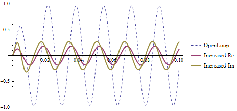
Moving the poles either further to the left or away from the real axis decreases the magnitude response.
In[9]:=
X
Plot[{y0, y1, y2}, {t, 0, .1}, PlotRange -> All, PlotStyle -> {Dashed, Thick, Thick, Thick}, PlotLegends -> {"OpenLoop", "Increased Re", "Increased Im"}, ImageSize -> Medium]
Out[9]=