8ビット加算器
二進加算器は基本的な演算操作のためのコンピュータでよく使われるデジタル回路です.Modelica標準ライブラリのDigitalライブラリを使って,2個の8ビット整数を取りその和を計算する8ビット加算器を作成しました.
8ビット加算器の原理
8 ビット加算器は以下の回路図に示すように,数字を1桁ずつ加算します.この例では,整数170と51はそれぞれ入力aとbを表し,結果の出力は合計221です.最初の加算器には下位桁からの繰上がりがないため,全加算器(FA)ではなく半加算器(HA)で表されます
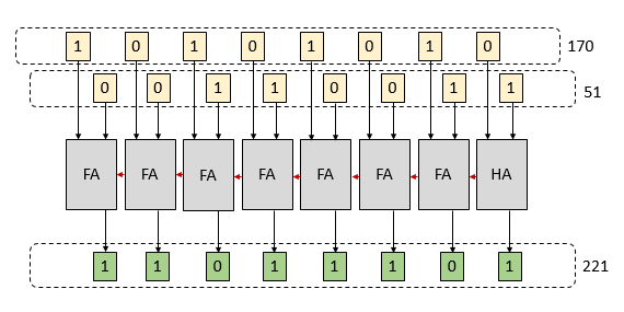
この回路図は,半加算器と全加算器を使用して2つの8ビット整数の和を計算する原理を説明している.
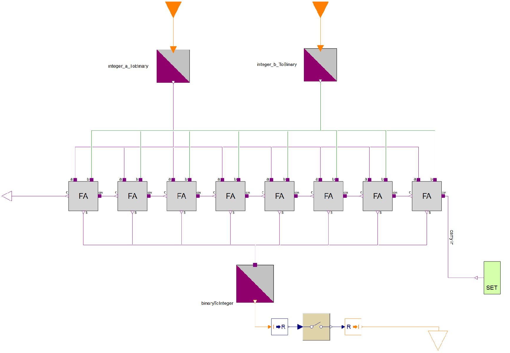
計算機モデルを1レベル下に進むと,1つの加算器の出力cが別の加算器の入力cinを構成する,8つの全加算器が確認できる.右端の加算器は,SETコンポーネントが繰上がり0を返すため,実際には半加算器である.その他の加算器入力(aおよびbで示される)はもとの整数から変換された二進数である.ダイアグラムの下部の最後のステップは,二進数の結果を最終的な整数の合計に変換することを示している.
シミュレーション結果
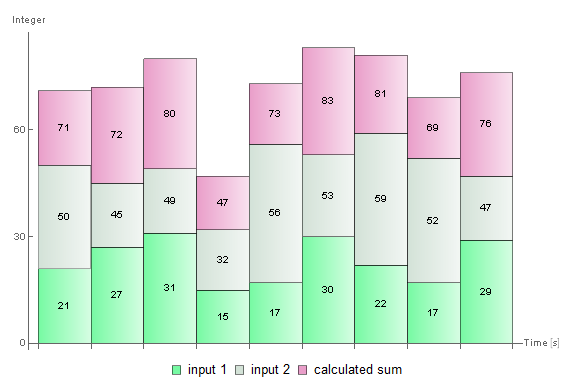
計算機への入力はModelica標準ライブラリのIntegerTableを使用して変更される.整数の各集合について和が計算され,シミュレーションが行われる.
Wolfram System Modeler
評価版
ご購入
System ModelerはWindows,macOS,
Linuxで日本語と英語でご利用になれます »
ご質問やコメントはWolframエキスパートまでお寄せください »