Convertidor reductor-elevador
Los convertidores reductor-elevador se utilizan tanto para aumentar el voltaje de un nivel inferior a uno superior como para reducir el voltaje de un nivel superior a uno inferior. Podemos encontrar convertidores reductor-elevador en aplicaciones en las cuales el voltaje de suministro cambia con el tiempo, tales como aplicaciones alimentadas por batería.
Para ejecutar este ejemplo necesitará
Las versiones más recientes de System Modeler y Mathematica.
Por favor haga una selección:
Obtener unaprueba gratuita Continuar
con la descarga
El modelo
Un convertidor reductor-elevador es un convertidor de potencia conmutada que utiliza dos interruptores (usualmente un diodo y un transistor), un inductor y un condensador para convertir el voltaje de corriente continua de un nivel inferior a uno superior, o a la inversa. Cuando el interruptor está encendido, la corriente pasa a través del inductor y aumenta la energía allí. Cuando el interruptor está apagado, la corriente del inductor pasa a través de la carga y el diodo. Se agrega un condensador de filtro para suavizar el voltaje de salida.
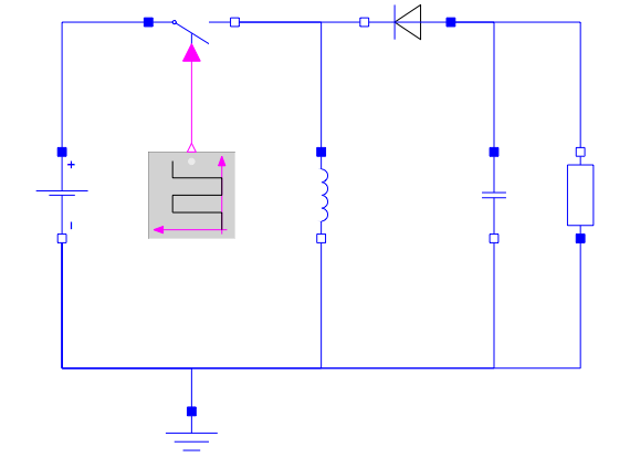
Un modelo de un convertidor reductor-elevador creado en System Modeler a partir de componentes estándar.
Operación y relación de ciclo
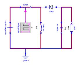
El interruptor está encendido, el inductor cargado, y el condensador proporciona la carga.
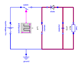
El interruptor está apagado, y el inductor proporciona la carga junto con el condensador.
La relación para la relación de conversión de voltaje  es dada por
  , donde la relación de trabajo
  es la relación de tiempo en que el interruptor está encendido en un ciclo. Con cero está apagado todo el tiempo, y con uno está encendido durante todo el ciclo. Con un
  por debajo de 0.5, el convertidor reducirá el voltaje, y por encima de 0.5, el convertidor aumentará el voltaje.
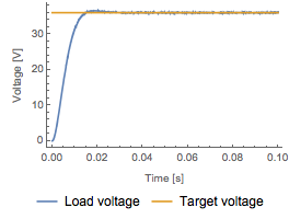
El voltaje se aumenta de voltaje 24 a 36, con una relación de trabajo  de 0.6.
de 0.6.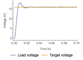
El voltaje se reduce de voltaje 24 a 16, con una relación de trabajo  de 0.4.
de 0.4.El convertidor reductor-elevador permite tanto niveles de voltaje más altos como más bajos. Esta mayor flexibilidad en comparación con los convertidores reductor y elevador tiene un costo: una mayor complejidad de circuito y una mayor presión sobre los componentes.
Detecte el modo discontinuo
Si la carga de salida está por debajo de un umbral determinado, la corriente del inductor se reducirá a cero durante un intervalo en el ciclo de conmutación; el convertidor entonces entra en el modo de conducción discontinua (DCM). Si la relación de trabajo no se modifica durante el DCM, el voltaje de salida puede aumentar a niveles peligrosamente altos, lo cual someterá a los componentes a una mayor presión y desgaste. En este caso utilizamos Wolfram Language para detectar el DCM.
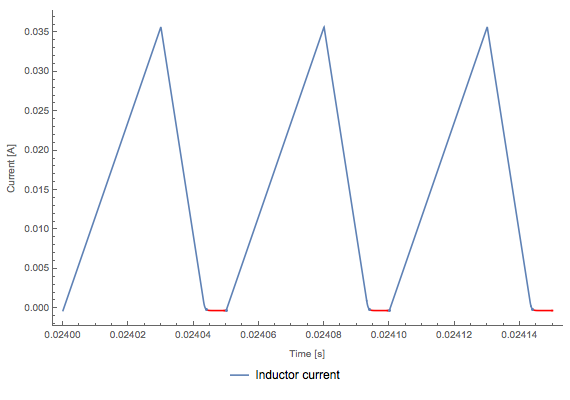
En DCM la corriente baja a cero dentro del ciclo de conmutación.
Analice resultados de simulación en Wolfram Language
Calcule distintas métricas, como el tiempo en DCM y el rizado de voltaje en el ejemplo descargable.
Wolfram System Modeler
Probar
Comprar
System Modeler está disponible en inglés
y japonés
para Windows, macOS y Linux »
¿Preguntas? ¿Comentarios? Contacte a un experto de Wolfram »