電気工学
System Modelerを使うと,電気回路,パワーエレクトロニクス,電気機械を構築し,研究することができます.電気と機械のコンポーネントを組み合せて完全なシステムモデルを構築したり,解析タスクを実行して性能を測定したりできます.
Buck Converter
Using a linear DC‐to‐DC regulator is one of the simplest ways to reduce the voltage of a DC supply. However, as linear regulators work by converting excess power to heat, they are highly inefficient and inconvenient to use in many applications. A common alternative to reduce DC voltage is instead to use a buck converter. Buck converters can be found in a large number of applications, including the conversion of the main voltage in computers to a lower level that can be used by processors.
The Model
A buck converter is a switched-mode power supply that uses two switches (usually a diode and a transistor), an inductor, and a capacitor to convert direct current voltage from a higher to a lower level. When the switch is turned off, the inductor current freewheels through the diode. When the switch is turned on, the inductor current increases and doesn’t pass through the diode. In this example, we study the difference in efficiency between a buck converter and a simple (linear) Zener regulator when converting a supply voltage (Vin) of 24 V to an output voltage (Vout) of 12 V.
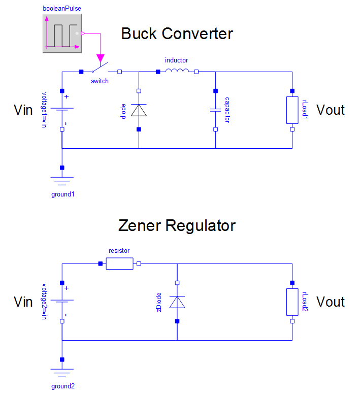
A model of a buck converter and Zener regulator created in SystemModeler from standard components.
Simulation Results
Both the buck converter and Zener regulator produce an output voltage of 12 V and a load current of 1 A. Note, however, the ripple effect caused by the buck converter. Output ripple is one of the main disadvantages of using a switched-mode power supply.
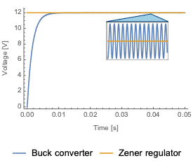
Output voltage. The inset shows the output voltage ripple.
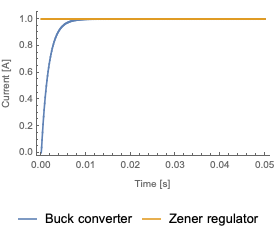
Load current.
Although suffering from output voltage ripple, buck converters are far more efficient than linear regulators due to the fact that very little energy is being wasted in resistive losses. In this particular case, the buck converter has been modeled using an ideal power switch and inductor, which makes its efficiency slightly unrealistic. However, even when non‐ideality is accounted for, buck converters can still reach an efficiency of 95% or more.
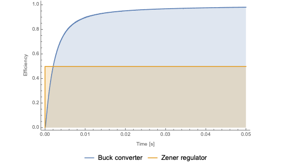
The efficiency of the buck converter and Zener regulator circuits, displayed as the ratio between the input energy provided by the voltage source and the output energy at the load. As can be seen, about 50% of the input energy in the Zener regulator circuit is lost as heat, while the buck converter reaches an efficiency of almost 100%.
Wolfram System Modeler
評価版
ご購入
System ModelerはWindows,macOS,
Linuxで
日本語と英語でご利用になれます »
ご質問やコメントはWolframエキスパートまでお寄せください »