Ingeniería eléctrica
Utilice System Modeler para construir y estudiar circuitos eléctricos, electrónica de potencia y maquinaria eléctrica. Combine componentes eléctricos y mecánicos para crear modelos de sistemas completos. Realice tareas de análisis y mida el rendimiento.
Potentiometers
Para ejecutar este ejemplo necesitará
Las versiones más recientes de System Modeler y Mathematica.
Por favor haga una selección:
Obtener unaprueba gratuita Continuar
con la descarga
The Model
In its normal configuration, a potentiometer acts as a variable voltage divider. If a voltage source is connected between the two pins, called terminals, the voltage over the third pin, known as the wiper, will vary with the position of the potentiometer shaft. This shaft can, for example, be controlled by a slider or a thumbwheel.
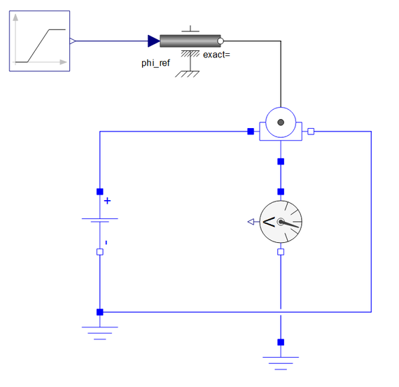
When the thumbwheel is turned, the voltage over the voltage sensor will vary. Most often, the potentiometer contains a resistive element whose resistance increases linearly with its length. The wiper pin slides across this resistive element, causing the resistance between one terminal and the wiper to decrease while the resistance between the other terminal and the wiper increases. The voltage from the wiper pin will be equal to the input voltage times the resistance from the wiper pin to the ground divided by the potentiometer’s total resistance.
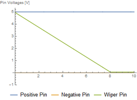
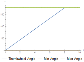
Explore Simulation Results
Plots can be stored in Simulation Center and easily brought up the next time the model is simulated. All models in this example contain stored plots.
Using the Potentiometer
Reuse Components
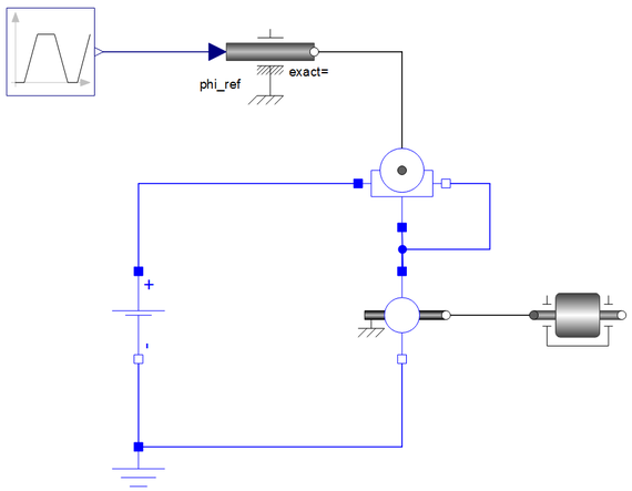
A custom component created in SystemModeler can often be reused in different configurations.
A thumbwheel potentiometer can be connected in a rheostat configuration, working as a variable resistor. The terminal pin connected to the ground is then short-circuited with the wiper pin. This means that the voltage over the terminal to the wiper will be the same as over the two terminals. The rheostat has been connected in a series with a motor. The motor in turn drives a body with inertia. The torque produced by the motor will be proportional to the current running through the motor. Since the motor is connected in a series with the potentiometer, the current through the motor will be the same as the current through the potentiometer. By turning the potentiometer, the motor torque can be controlled.
Wolfram System Modeler
Probar
Comprar
System Modeler está disponible en inglés
y japonés
para Windows, macOS y Linux »
¿Preguntas? ¿Comentarios? Contacte a un experto de Wolfram »