自動車と輸送
System Modelerを使って,車両ダイナミクス,パワートレインコントローラ,シャーシ,安全システム等を設計し,そのシミュレーションを実行します.Mathematicaと組み合わせて,制御系の設計および最適化を行います.
Servo with Control
Hydraulic servo systems are commonly used in a variety of industrial applications, such as the machine-tool industry. In this example of a hydraulic servo, a directional control valve is used to route fluid to and from a cylinder with the purpose of moving a load to different specified positions.
The Servo Model
The pump component pumps fluid from tank1 to the control valve, which then directs the fluid into either the right or left chamber of the double cylinder, depending on whether the load should be moved to the left or to the right.
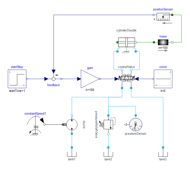
The servo model as seen in the diagram view in Wolfram SystemModeler.
Simulation Results
Study the simulation plots below to see how the directional control valve shifts its position to allow fluid to flow into either the left or right chamber, and how this ultimately moves the load to different positions.
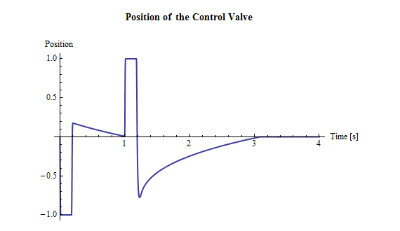
The plot shows how the position of the control valve shifts from the left (-1), to the center (0), to the right (1), and then back to the center again.
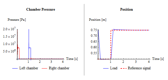
The left plot (Chamber Pressure) shows how the pressure changes in the left and right chamber. This, of course, correlates to the reference signal that is fed into the system (seen in the right plot together with the actual load position). When the load is moved from 0.75 m to 0.5 m, fluid flows into the right chamber and the pressure builds up. The opposite goes for the move from 0.75 m to 0.5 m, during which pressure increases in the left chamber.
Wolfram System Modeler
評価版
ご購入
System ModelerはWindows,macOS,
Linuxで
日本語と英語でご利用になれます »
ご質問やコメントはWolframエキスパートまでお寄せください »