Otros
Ejemplos de uso de un amplio rango de áreas de aplicación para aprender sobre modelado y simulación con System Modeler y el lenguaje Modelica.
Buck-Boost Converter
Buck-boost converters are used both to step up voltage from a lower level to a higher level and to step down voltage from a higher level to a lower level. Buck-boost converters can be found in applications where the supply voltage changes over time, such as battery-powered applications.
Para ejecutar este ejemplo necesitará
Las versiones más recientes de System Modeler y Mathematica.
Por favor haga una selección:
Obtener unaprueba gratuita Continuar
con la descarga
The Model
A buck-boost converter is a switched-mode power converter that uses two switches (usually a diode and a transistor), an inductor, and a capacitor to convert direct current voltage from a lower to a higher level, or the other way around. When the switch is turned on, the current goes through the inductor and increases the energy there. When the switch is turned off, the inductor current goes through the load and the diode. A filter capacitor is added to smooth out the output voltage.
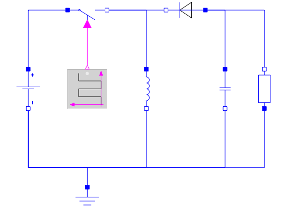
A model of a buck-boost converter created in SystemModeler from standard components.
Operation and Duty Ratio
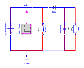
The switch is turned on, the inductor is charged, and the capacitor supplies the load.
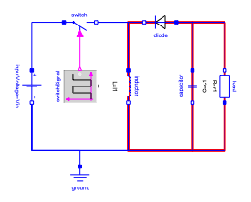
The switch is turned off, and the inductor supplies the load together with the capacitor.
The relationship for the voltage conversion ratio  is given by
  , where the duty ratio
  is the ratio of time the switch is on in one cycle. With zero it is off all the time, and with one it is on for the whole cycle. With a
  below 0.5, the converter will step down the voltage, and above 0.5 the converter will step up the voltage.
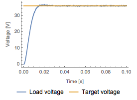
Voltage is stepped up from 24 to 36 voltage with a duty ratio  of 0.6.
of 0.6.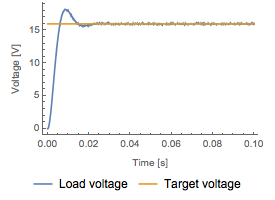
Voltage is stepped down from 24 to 16 voltage with a duty ratio  of 0.4.
of 0.4.The buck-boost converter allows for both higher and lower voltage levels. This increased flexibility compared to the buck and boost converters comes at a price: higher circuit complexity and higher stress on the components.
Detect Discontinuous Mode
If the output load is below a certain threshold, the inductor current will drop to zero during an interval in the switching cycle; the converter then enters discontinuous conducting mode (DCM). If the duty ratio is not changed during DCM, the output voltage can climb to dangerously high levels and the components will see increased stress and wear. Here the Wolfram Language is used to detect DCM.
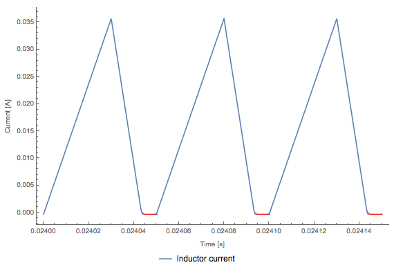
In DCM the current goes to zero within the switching cycle.
Analyze Simulation Results in the Wolfram Language
Calculate different metrics, such as time in DCM and voltage ripple in the downloadable example.
Wolfram System Modeler
Probar
Comprar
System Modeler está disponible en inglés
y japonés
para Windows, macOS y Linux »
¿Preguntas? ¿Comentarios? Contacte a un experto de Wolfram »