Otros
Ejemplos de uso de un amplio rango de áreas de aplicación para aprender sobre modelado y simulación con System Modeler y el lenguaje Modelica.
Full-Wave Bridge Rectifier
Many applications require direct current, DC. However, transporting direct current through the power lines has several disadvantages compared to alternating current, AC. AC can be used in transformers and allows for higher-efficiency power conversion and transmission. For the electricity found in power outlets to be used in DC circuits, it first needs to be converted into direct current. One way to do this is to use a full-wave bridge rectifier.
Para ejecutar este ejemplo necesitará
Las versiones más recientes de System Modeler y Mathematica.
Por favor haga una selección:
Obtener unaprueba gratuita Continuar
con la descarga
The Model
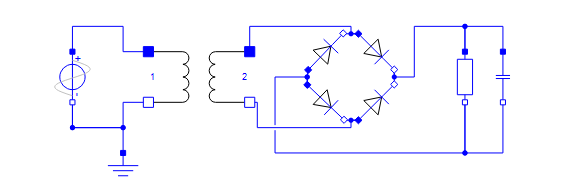
The full-wave bridge rectifier contains four forward-biased diodes. Depending on the polarity of the source, the current will flow through two of the diodes. This will cause the current to enter the load only through the positive pin, regardless of the source polarity. A full-wave bridge rectifier often uses a transformer on the AC side to step down the voltage from the power outlet and a capacitor on the DC side to smooth out ripples from the diode bridge.
Understanding the Circuit
To better understand the flow of current through the circuit, it can be visualized using dynamic diagrams in SystemModeler together with Mathematica.
Dynamic Diagrams
Animate the diagram based on simulation results.
The blue arrows show the direction of the current before it enters the load, while the red arrow shows the direction of the current after it has passed through the load. Notice how the diodes switch based on the source polarity. The animation was created using SystemModeler dynamic diagrams and visualized in Mathematica.
Explore and Compare
SystemModeler can be used to easily compare different design decisions. Here is a comparison of the usage of two different types of forward-biased diodes in the circuit.
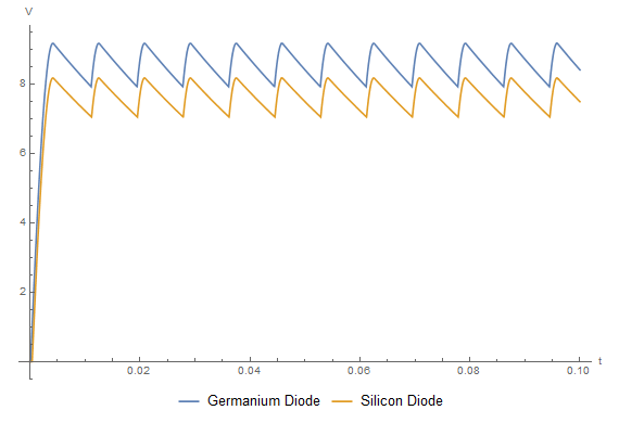
The different diodes have different voltage thresholds, which results in different voltage profiles over the load.
Design Decisions
Use SystemModeler to try different scenarios and make design decisions based on your needs.
Several different static equations exist to describe the output ripple from the rectifier. As a usual rectifier contains a dynamical component, a capacitor, these equations can only be approximations. Using SystemModeler to simulate the system results in a more accurate value of the output ripple. The simulation value can also be compared to the approximated value using Mathematica.
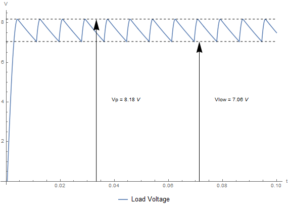
Ripple voltage over the load from simulation. Calculations give:  .
.
.A static approximation between circuit parameters and ripple amplitude is the following: 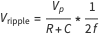 , where
  is the load resistance,
  is the capacitor filter capacitance, and
  is the source voltage frequency. Using the same parameters as the simulation above, the static approximation gives a voltage ripple of 1.45 V. The static approximation is only valid when the ripple is sufficiently small.
Wolfram System Modeler
Probar
Comprar
System Modeler está disponible en inglés
y japonés
para Windows, macOS y Linux »
¿Preguntas? ¿Comentarios? Contacte a un experto de Wolfram »