Adjust the Color and Brightness of an RGB LED
A microcontroller is a digital device, but many real-world signals are analog. The microcontroller reads analog input signals by converting them to digital signals using analog to digital conversion (ADC). The microcontroller generates analog output signals using pulse width modulation (PWM).
show complete Wolfram Language input
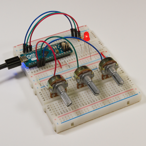
In this example, you will program an Arduino Micro to control the color and brightness of an RGB LED using potentiometers. The three potentiometers are connected to pins A0, A1 and A2 of the Arduino Micro. The three pins of the RGB LED are connected to the PWM pins 9, 10 and 11.
The systems model.
The inputs.
The outputs.
The complete microcontroller specification.
The connection port to the target.
Deploy the code.
