Filter I2C Data
In Inter-Integrated Circuit (I2C) communication, a master device can talk to up to 128 slave devices. Each slave is identified by a unique address and the data transfer happens on the Serial Data (SDA) line. The other line is the Serial Clock (SCL) line. I2C is also known as the Two-Wire Interface (TWI).
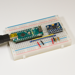
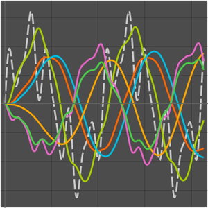
In this example, code is deployed to an Arduino Nano to obtain accelerometer and gyro readings from an MPU-6050 I2C sensor. The orientation angle of the sensor can be computed from the accelerometer or gyro readings. These computations are inaccurate because the former is noisy and the latter drifts during steady state. So a complementary filter is also deployed that blends the two values. The unfiltered and filtered values will be sent back over the serial bus and visualized.
The acceleration along the  and
and  axes, the temperature and the angular velocity along the
  axis are stored in two bytes, each starting at address 0x3D. Following is the specification to get these 8 bytes.
The initialization specification.
The MPU-6050's address is 0x68. Here is its complete specification.
The conversion for each input channel.
The complete microcontroller specification.
A prefilter block computes the angle from the accelerometer data in degrees and also the angular rate in degrees per second from the gyroscope data.
A complementary filter takes the prefilter outputs and computes a filtered angle value.
An integrator computes the angle just by integrating the angular rate.
The complete systems model.
Deploy the code.
Open a connection to the Arduino Nano.
Submit a task to read the data.
Parse and plot the data.
Remove the task and close the connection to the device.
