Contador binario
Los contadores se utilizan en una amplia variedad de aplicaciones digitales como una manera de contar eventos. En este ejemplo, hemos construido un contador ascendente asíncrono simple de 4 bits utilizando la biblioteca Digital, la cual forma parte de la Biblioteca estándar de Modelica.
Para ejecutar este ejemplo necesitará
Las versiones más recientes de System Modeler y Mathematica.
Por favor haga una selección:
Obtener unaprueba gratuita Continuar
con la descarga
Modelo de contador
Los contadores pueden ser utilizados en una amplia variedad de aplicaciones. Por ejemplo, pueden ser usados para contar pulsos de un sensor conectado a una rueda para contar el número de revoluciones, lo cual a su vez puede ser usado para calcular la velocidad de la rueda. Los contadores también pueden ser utilizados como relojes digitales para distintos propósitos. Los contadores digitales tienen otro uso en las unidades de procesamiento central (CPU), donde un tipo específico de contador (contadores de programa o PC) se utiliza como una manera para que la CPU pueda recorrer las instrucciones del programa, una por una, desde una memoria. El modelo en este ejemplo consiste en un contador ascendente asíncrono de 4 bits, al que se le alimenta con un pulso de reloj de 1 Hz. A continuación se muestra un diagrama del modelo.
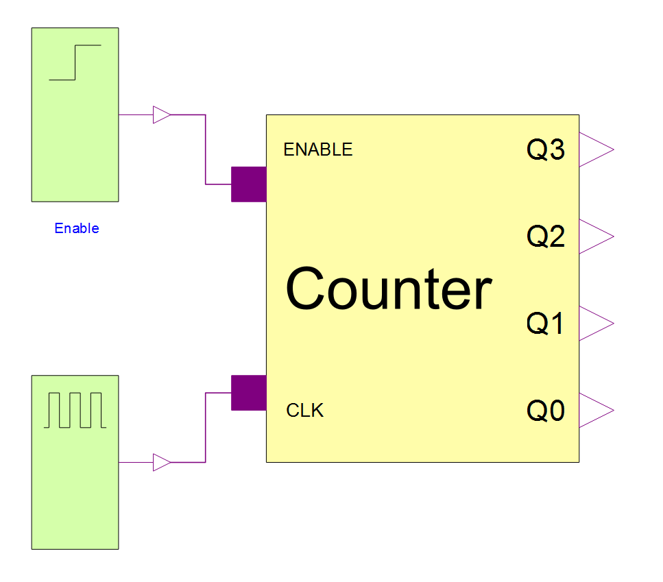
Vista de diagrama del modelo. El contador en el diagrama es alimentado por un pulso de reloj y una señal de habilitación que indica al contador cuándo contar y cuándo pausar.
Los biestables o flip-flops se utilizan como componentes básicos en los circuitos digitales y funcionan como una especie de memoria que almacena el estado de un bit. Al usar múltiples biestables, es posible construir máquinas de estado digitales. Un contador binario es, básicamente, una máquina de estado que simplemente recorre sus estados para cada ciclo de una señal de reloj. El biestable JK es considerado como el diseño de biestable más universal, y puede usarse como diferentes tipos de biestables con tan solo ajustar cómo se conectan las entradas a los terminales J y K. En este ejemplo, los biestables se utilizan con una función de conmutación, lo cual significa que la salida cambia para cada ciclo completo del reloj. Esto se logra alimentando unos en los pines J y K de los biestables. Al colocar únicamente ceros en todos los terminales J y K la salida nunca cambiará, sin importar la entrada. Esto lo hace adecuado para conectar todos los terminales J y K como una señal de habilitación para el circuito.
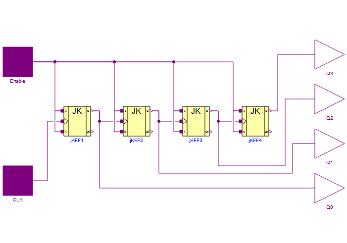
Vista de diagrama del modelo de contador.
El contador en este ejemplo es un contador asíncrono de 4 bits basado en biestables JK. Los biestables están conectados con sus terminales J y K al pin de habilitación, lo cual los coloca en "modo de conmutación. El biestable a la izquierda, que produce la señal Q0, cambiará su estado de salida para cada flanco descendente de la señal de reloj, por ejemplo, un reloj de CPU. Dado que la salida conmutará para cada flanco descendente del reloj, el reloj conmutará dos veces por cada conmutación de la salida.
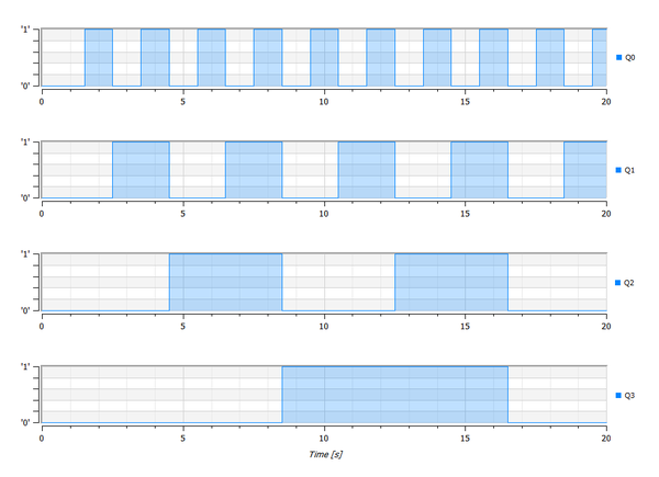
Este diagrama de una simulación muestra cómo los niveles lógicos de los cuatro bits cambian a lo largo del tiempo. La señal de habilitación pasa de 0 a 1 después de un segundo.
Wolfram System Modeler
Probar
Comprar
System Modeler está disponible en inglés
y japonés
para Windows, macOS y Linux »
¿Preguntas? ¿Comentarios? Contacte a un experto de Wolfram »