二進カウンター
カウンターは事象を数える方法としてさまざまなデジタルアプリケーションで使われています.この例では,Modelica標準ライブラリの一つであるDigitalライブラリを使って,4ビット非同期アップカウンターを作成します.
カウンターのモデル
カウンターはさまざまな用途に使用できます.例えば,車輪に取り付けられたセンサーからのパルスを数えて回転数を数え,その回転数から車輪の速度を計算することができます.カウンターはさまざまな目的のデジタル時計として使用することもできます.デジタルカウンターのもう一つの一般的な用途は,中央処理装置(CPU)です.CPUでは,特定の種類のカウンター(プログラムカウンターまたはPC)が,メモリからプログラム命令を1つずつ処理する方法として使用されます.この例のモデルは,1Hzのクロックパルスで供給される4ビットの非同期アップカウンターで構成されています.以下にモデルのダイアグラムを示します.
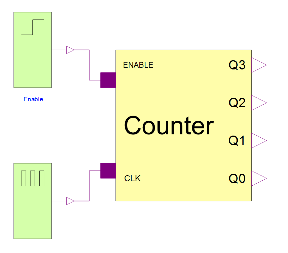
モデルのダイアグラム ビュー.ダイアグラム内のカウンターには,クロックパルス,そしてカウンターに数えるときと一時停止するときを指示するイネーブル信号が供給される.
フリップフロップまたはラッチは,デジタル回路の基本コンポーネントとして使用され,1ビットの状態を格納する一種のメモリとして機能します.複数のフリップフロップを使用することで,デジタルステートマシンが構築できます.二進カウンターは基本的に、クロック信号の各サイクルで状態を循環するステートマシンです.JKフリップフロップは最も汎用的なフリップフロップ設計であると考えられており,J端子とK端子への入力方法を調整するだけで,さまざまな種類のフリップフロップとして使用できます.この例では,フリップフロップはトグル機能で使用されます.つまり,完了したクロックサイクルごとに出力が変更されるのです.これはフリップフロップのJピンとKピンの両方に1を入力することで実現されます.すべてのJ端子とK端子に0のみを配置すると,入力が何であれ,出力が変化することはありません.これにより,すべてのJ端子とK端子を回路のイネーブル信号として接続するのに適したものとなります.
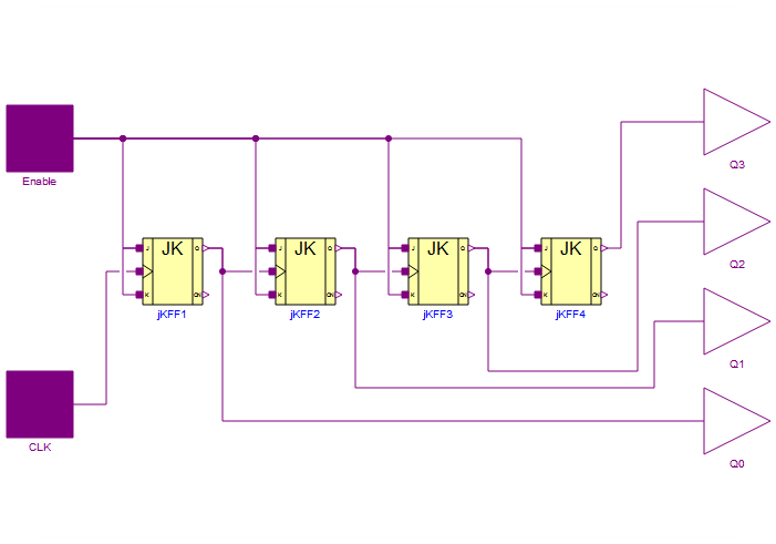
カウンターモデルのダイアグラムビュー
この例のカウンターは,JKフリップフロップに基づく4ビットの非同期カウンターです.フリップフロップは,J端子とK端子の両方がイネーブルピンに接続され,「トグル モード」になっています.Q0信号を生成する左側のフリップフロップは,CPUクロック等のクロック信号の立下がりエッジごとに出力状態を変更します.出力はクロックの立下がりエッジごとに切り替わるため,出力のトグルごとにクロックが2回切り替わります.
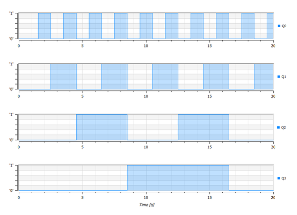
このシミュレーションの図は,4つのビットの論理レベルが時間の経過とともにどのように変化するかを示している.イネーブル信号は1秒後に0から1に変わる.
Wolfram System Modeler
評価版
ご購入
System ModelerはWindows,macOS,
Linuxで日本語と英語でご利用になれます »
ご質問やコメントはWolframエキスパートまでお寄せください »