点滅するLED:デジタル回路ラボ
デジタル回路はパソコンからスマートTVまでいたるところで見られます.この例ではデジタル回路がどのように動作するかを学び,基本的な回路を作成します.最後にはArduinoを使って,自作のデジタル回路をハードウェアに接続することでテストします.
モデルの作成
このモデルは,Arduinoに接続されたデジタル入力とデジタル出力で構成されています.デジタル入力信号はマルチプレクサの状態を設定するために使用されます.マルチプレクサの状態に基づいて,事前に定義された周波数のブールパルスが選択されます.
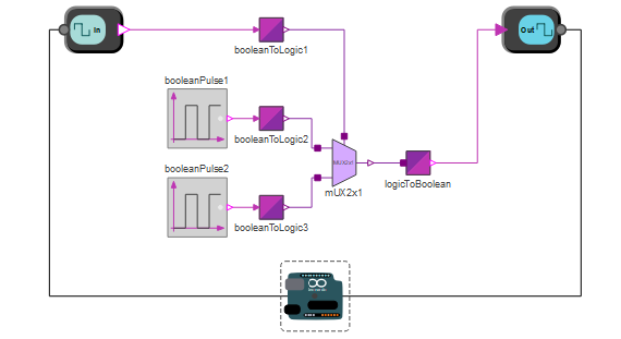
2つの異なる周波数を切り替えるために2×1のマルチプレクサが使われる.
モデルのテスト
プッシュボタンを使って点滅するLEDの周波数を変更します.
プッシュボタンはArduinoのピン9に接続され,LEDはピン6に接続される.
Wolfram System Modeler
評価版
ご購入
System ModelerはWindows,macOS,
Linuxで日本語と英語でご利用になれます »
ご質問やコメントはWolframエキスパートまでお寄せください »