Ingeniería eléctrica
Utilice System Modeler para construir y estudiar circuitos eléctricos, electrónica de potencia y maquinaria eléctrica. Combine componentes eléctricos y mecánicos para crear modelos de sistemas completos. Realice tareas de análisis y mida el rendimiento.
Flip-Flop
Flip‐flops are digital logic circuits commonly used in processes where there is a need for digital data storage and transfer. In this example we will use the Digital library, a part of the Modelica Standard Library, to demonstrate the use of basic logic gates in a pulse‐triggered master‐slave flip‐flop.
Flip‐Flop Model Structure
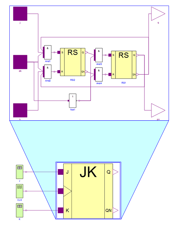
The smaller bottom image shows the flip‐flop top model as seen in the diagram view in Wolfram SystemModeler. As can be seen, the flip‐flop has three different inputs: two tables j and k containing values and a clock source CLK that provides the pulses. Going down one level into the component named JK (the expanded image at the top), we see some of the basic gates denoted And1, And2, And3, And4, and Not1. The output from these gates is calculated using the corresponding truth table.
Simulation Results
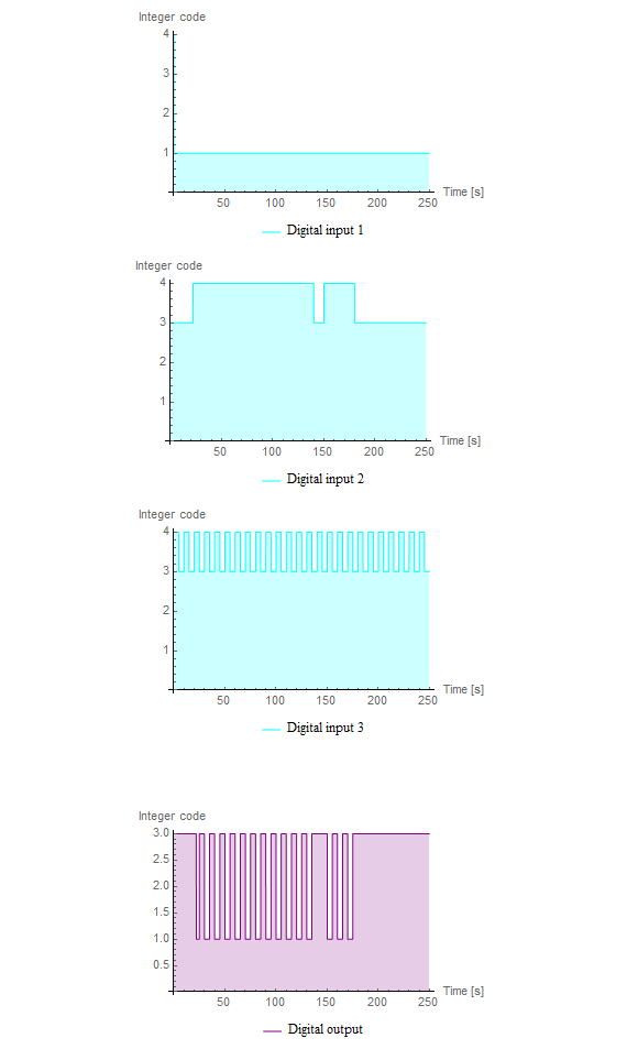
These are the simulated results of the And2 component in the flip‐flop model. This particular gate has three different inputs (shown in the top three subplots). The output, calculated from the corresponding truth table for an And basic logic gate, can be seen in the bottom subplot. In the digital library the integer codes correspond to different logic values: 1 = uninitialized, 3 = binary value 0, 4 = binary value 1.
Wolfram System Modeler
Probar
Comprar
System Modeler está disponible en inglés
y japonés
para Windows, macOS y Linux »
¿Preguntas? ¿Comentarios? Contacte a un experto de Wolfram »