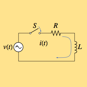
Find the Impulse Response of a Circuit
Find the impulse response for a circuit that is composed of a resistor  and an inductor
  , and is driven by a time-dependent voltage
  .
.
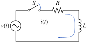
The current  can be computed by solving a linear first-order differential equation
  .
.
Set up the differential operator corresponding to the left-hand side of the ODE.
In[1]:=
voltage = L i'[t] + R i[t];Assume that the switch is initially open.
In[2]:=
init = i[0] == 0;Compute the impulse response for the circuit using GreenFunction.
In[3]:=
gf[s_, t_] =
 GreenFunction[{voltage, init}, i[t], {t, 0, \[Infinity]}, s]
Out[3]=
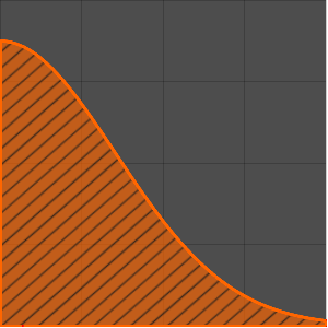
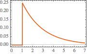
Plot the impulse response at  .
.
In[4]:=
Plot[gf[s, t] /. {s -> 1, R -> 2, L -> 4}, {t, 0, 7},
 PlotTheme -> "Scientific", AxesLabel -> {"t", "i[t]"}]
Out[4]=
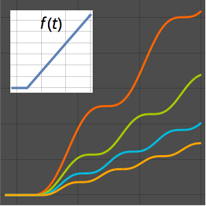
Compute the response of the circuit to a step voltage.
In[5]:=
v[t_] := HeavisideTheta[t];In[6]:=
current = Integrate[gf[s, t] v[s], {s, 0, t}, Assumptions -> t > 0]Out[6]=
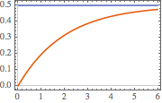
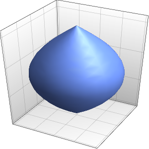
Visualize the step response.
In[7]:=
Plot[{current /. {R -> 2, L -> 4}, 0.5} // Evaluate, {t, 0, 6},
 PlotTheme -> "Scientific"]
Out[7]=